
The interfacing of the data bus is the simplest part. There are eight lines comprising the data bus of both 8085 and the memory chips. After completing these two connections, we are done with the control signals except CS. Similarly, for writing to a memory chip, MEMW will be connected to the WR pin of the RAM. So, MEMR will be connected to the OE pin.

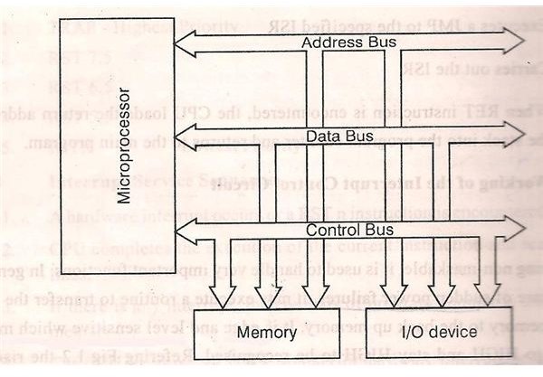
While reading from a memory chip, it’s output should be enabled. Since we are dealing with memory, we will just need MEMR and MEMW signals. The circuit for generating control signals is shown below.įour control signals are generated when we input the WR, RD and IO/ M signals from the 8085 to the 3:8 decoder – IOR, IOW, MEMR and MEMW. To read about the generation of control signals, you can read our post on Demultiplexing of Bus and Generating Control Signals. These will be connected to the control signals generated using a 3 to 8 decoder. In the memory chips, there are two pins for control signals – OE (Output Enable) and WR (Memory Write). Each of these buses will be connected to the memory chip. There are three types of buses in 8085 – Address bus, data bus, and control bus. For simplicity, we will not show these pins in the diagram. VCC and GND pins: These pins serve the purpose of powering the ICs.WR pin: Upon activation of this active-low memory write pin, data on the data bus is written on the memory chip at the location specified by the address bus.OE pin: When this active-low output enable pin is enabled, the memory chip can output the data into the data bus.The Chip Select (CS) pin is used for this. Basically, we select a chip only when it is needed. We need to generate this signal for each of the chips according to the range of addresses assigned to them.

CS pin: When this pin is enabled, the memory chip knows that the microprocessor is talking to it and responds to it accordingly.Similarly, the 2 kB RAM will have 2 11 different memory locations. Hence, it will have ten address lines A0 to A9. In this case, a memory of size 1 kB x 8 will have 2 10 different memory locations. Address pins: The number of address pins depends on the size of the memory.Data pins: Since each memory location stores eight bits, there are eight data lines D0-D7 connected to the memory chip.RAM and ROM both have same pins, except for WR pin, which is present in RAM and is not there in a ROM. The first step to solve this problem is to understand the pins of the given memory chips. You can assign the address range of your choice to the 2 kB RAM. The address allotted to 1 kB EPROM should be 2000H to 22FFH. Interface a 1kB EPROM and a 2 kB RAM with microprocessor 8085. Let us take up a problem regarding the interfacing of memory and solve it as we learn the topic.

Now, let us learn through an example, how external RAM and external ROM chips can be interfaced with 8085.


 0 kommentar(er)
